| (3 items) Lucky Duck Kennels feature a 5-star crash rating, lifetime warranty, and are lightweight and easy to load into any vehicle. Fits great in your pick-up, SUV, back seat, or side-by-side. Proudly made in the USA! ... |
|
|
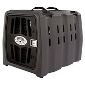
 | (3 items) Dakota 283 believes every dog owner should be able to afford protection for their pet with a high-quality kennel. That's why they created the Canine Rough and Tough Economy ("CRaTE") kennel. From backyard adventures to cross-country travel, the Dakota 283 CRaTE dog kennel is up for the challenge. Its lightweight yet sturdy design makes it easy to l... |
|
|
 | (12 items) Dakota 283 products are made in USA and built to withstand the test of time. Inspired by military storage design, Dakota 283 kennels are molded in one solid piece to handle all the abuse you and your dogs can give!... |
|
|
 | (4 items) The Mud River Dixie Insulated Kennel Cover has many features that will allow your dog protection from the cold and rain making your standard dog crate a warm, dry and comfortable place for your hunting dog. Features on the Dixie Dog Crate Cover include MicroLite3 insulation, a 2-ply infused 1200D Poly industrial grade bottom that is built to withst... |
|
|